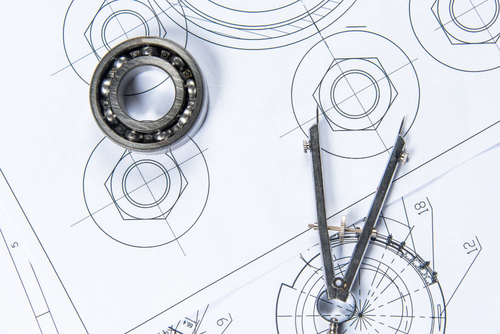
Mechanical drawings, also known as engineering drawings or mechanical engineering drawings, are graphical representations that convey detailed information about the design, dimensions, tolerances, and specifications of mechanical components, machines, devices, and systems. These drawings are used by mechanical engineers, designers, and manufacturers to communicate precise instructions for the fabrication, assembly, and operation of mechanical objects.
Mechanical drawing serve as a universal language that allows various stakeholders, including engineers, manufacturers, suppliers, and quality control personnel, to understand and reproduce a mechanical design accurately. These drawings provide essential information for the production process, ensuring that components are manufactured to the correct specifications and can be assembled and function as intended.
Key elements of mechanical drawings include:
- Views: Mechanical drawings typically include multiple views of the object, such as front, side, top, and isometric views, to provide a comprehensive understanding of its shape and geometry.
- Dimensions: Dimensions are provided to specify the size, length, width, height, and other measurements of the object. These dimensions ensure that the component is manufactured to precise specifications.
- Tolerances: Tolerances indicate the allowable variations in dimensions. They ensure that components can be assembled without interference or excessive clearance and that the final product meets quality standards.
- Geometric Symbols: Geometric symbols, such as concentric circles, parallel lines, and positional tolerances, convey information about the relationship between features and how they should be machined or assembled.
- Notes and Annotations: Notes and annotations provide additional information, clarifications, and instructions to the reader. These annotations help ensure that the design intent is properly understood and followed.
- Sections and Details: Section views cut the object to reveal its internal structure and features. Detail views focus on specific areas of the design to provide a closer look at intricate or complex components.
- Bill of Materials (BOM): A BOM lists all the individual components, materials, and quantities required to build the mechanical assembly or system.
- Assembly Drawings: Assembly drawings show how individual components fit together to form a complete mechanical system. These drawings provide a step-by-step guide for assembly.
- Exploded Views: Exploded views illustrate how the individual components of an assembly come together by showing them separated and positioned in space.
- Sectional and Auxiliary Views: Sectional views cut away part of an object to reveal internal details, while auxiliary views provide additional angles or information that cannot be fully understood from the main views.
Mechanical Drafts are typically created using computer-aided design (CAD) software, which allows for precise measurements, easy editing, and the creation of detailed, scaled drawings. These drawings are essential for ensuring that products are manufactured accurately, meeting design specifications and quality standards. They are also crucial for documentation, communication, and collaboration among various teams involved in the design, manufacturing, and assembly processes.


